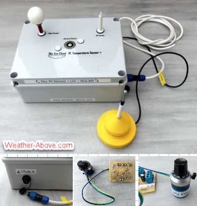

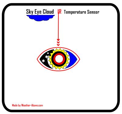
Cloud IR sky temperature sensor + UV and Solar +Light + Rain
Welcome to Weather-Above


Schematic artwork, Circuit board artwork where redrawn from diagrams supplied by "Niko of weather-watch" functional test programmes supplied by "Niko of weather-watch" Thank you for all the help. Circuit boards, were made in-house assembled and tested Weather-Above.com
Made by Michael Parry-Thomas

Top of the box logo artwork
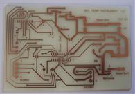
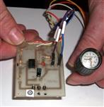
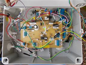
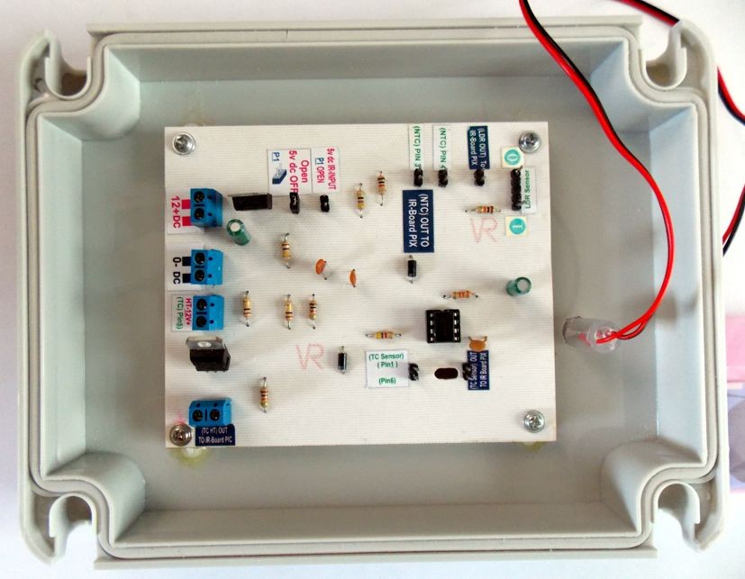
IR cloud circuit board made in-house
redrawn from diagrams supplied by "Niko of weather-watch"
Terminal connections layout
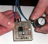
Components layout
Enclosure box layout
Cutout white circle to allow infrared sensor full view of sky

To make the heater I used a graphics card heatsink ,I used a 8 mm drill bit to drill a hole , the infrared sensor has a small flange on the bottom this is in contact with the heatsink, if the hole is drilled to big the infrared sensor will pass straight through

Mounted on the heatsink is a wire wound resistor. This is fixed in place with some high-temperature epoxy resin and a metal spring clip Which is in contact with the resistor and fixed in between the heatsink grooves

USB 2.0 to RS232 Serial Port DB9 9 Pin Male Converter Adapter Cable this will Convert the Sky Eye Cloud IR Temperature sensor to use a USB port on the PC instead of a RS 232 serial port
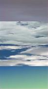
The Sky temperature will drop to the relevant cloud conditions , from ( Overcast, Cloudy, Partly Cloudy, Clear ) Night Time -10 to -27° , the lower the sky temperature to clear the sky (Clarity 50 -- 0)
New Sky Infrared cloud temperature sensor
with Inputs for UV and Solar add-on modules
, Plus Rain and Light modules
10/03/1216 New PCB Mod White Borads
The sky infrared sensor has a RS 232 connection coming from the device this connects to the computer, I am using a converter which allows me to use it on a USB port {USB 2.0 to RS232 Serial Port DB9 9 Pin Male Converter Adapter) the sensors are mounted on the top of my garage roof which is approximately 45 m away from my computer. The main infrared circuitboard has been made to allow additional modules UV and solar , to get the data from the sensors. I am running a small script that runs in Python shell which is running on Windows XP and is being tested on Windows 7 ,the script receives the data from the sensors and Writes the information to a log file which is then uploaded to my website where the data is turned into a graph. Weather display software as an option to read the log file which uses the cloud infrared temperature has a night time cloud sensor, with the two add-on modules weather display uses the UV and solar from the log file
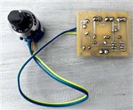
UV module
Solar module
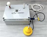
Sky cloud infrared project,sensors, (1) solar sensor (2) ambient temperature sensor (3) iinfrared cloud temperature sensor, (4) UV sensor,
1
2
3
4
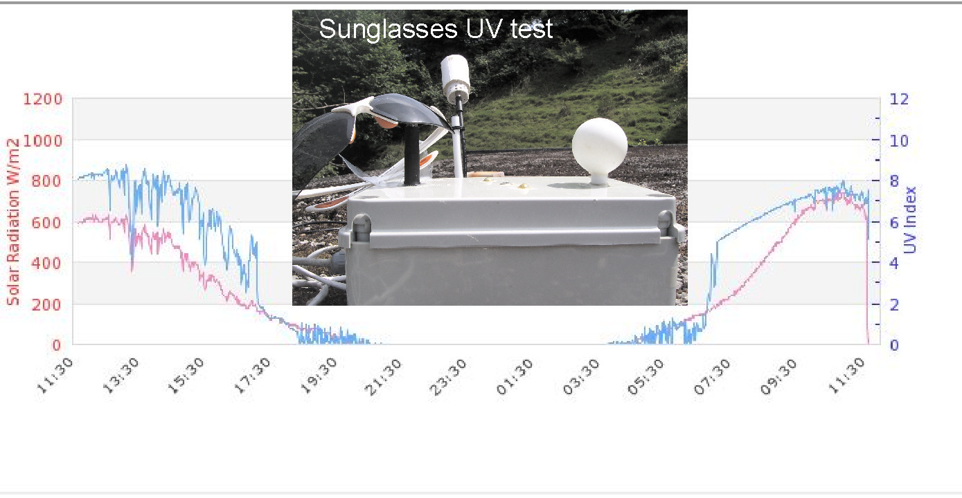
Sunglasses UV test
I've put over the UV sensor a pair of sunglasses to block out all UV, you can see in the graph that the UV dropped to (0) The UV sensor and sky cloud sensor , solar sensor are calibrated
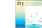
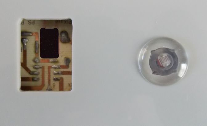
I have finally managed to get hold of some of the ceramic rain capacitor sensors. The sensor is connected to a another circuit board which as a op amp chip TLV2472 which connects to the ceramic rain capacitor sensor .On the circuit board there are inputs and outputs for a LDR sensor and connecting pins for N TC/heater. On the underside of the ceramic rain capacitor sensor a temperature sensor DS18B20 has been adhered to it ,this will be used in script code to monitor the temperature surface.

add on Rain + Light sensor interface board
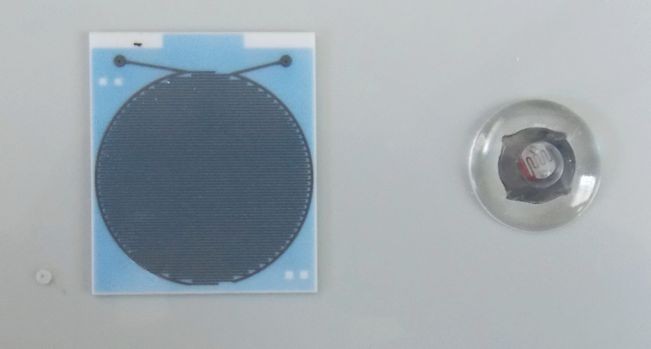
Ceramic rain capacitor sensor
Plus light sensor
Cutout hole in circuit board
To allow very short connections
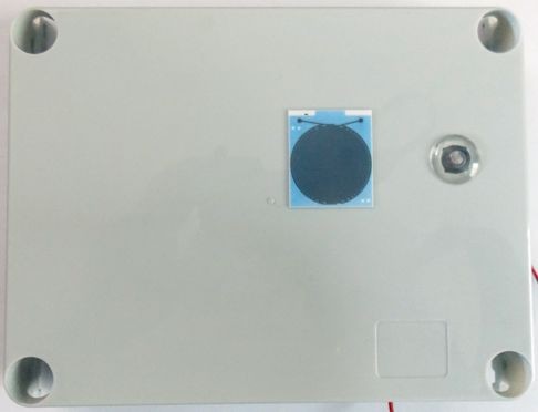
To mount the ceramic rain sensor to the box, I am using a product called High Temperature 704 Electronic Silicon Rubber Adhesive Sealant Glue
Updated 17/03/2018
The sky infrared temperature sensor is on line , refurbished for the main Infrared circuit board is complete. The uv - rain - light - solar radiation add-on module is complete and online . Solar sensor and the UV sensor will need to be calibrated this will be small adjustments made over several weeks
.jpg)
.jpg)
Taken out prototype boards and replace them with new printed circuit boards which have output pins for the add-on modules, all new connections are using a waterproof plug and socket system with double lock seal
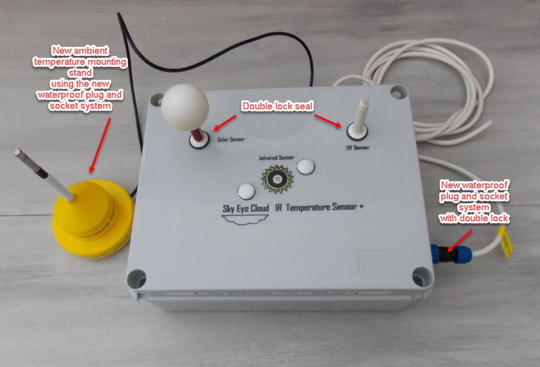
New refurbishment sensors have a double lock seal system and a new mounting holder for the ambient air temperature
All cable connections are using a waterproof socket plug system this makes it easier for any maintenance