
Welcome to Weather-Above
How to Make the Sky IR Sensors + UV ,Solar,Light ,
Soldering infrared circuit board
There are some links that need to be connected on the circuit board, please see diagram below links are indicated by the blue wire
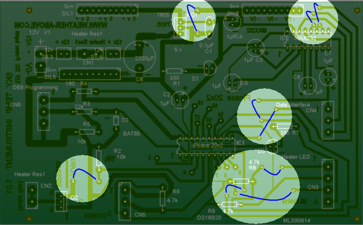
Once you have got your circuit board, start soldering the smaller component first, resistors, diodes, links capacitors, etc
Top view of the circuit board with components
Please click on the image for a larger size
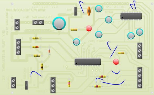
X-ray view of the links
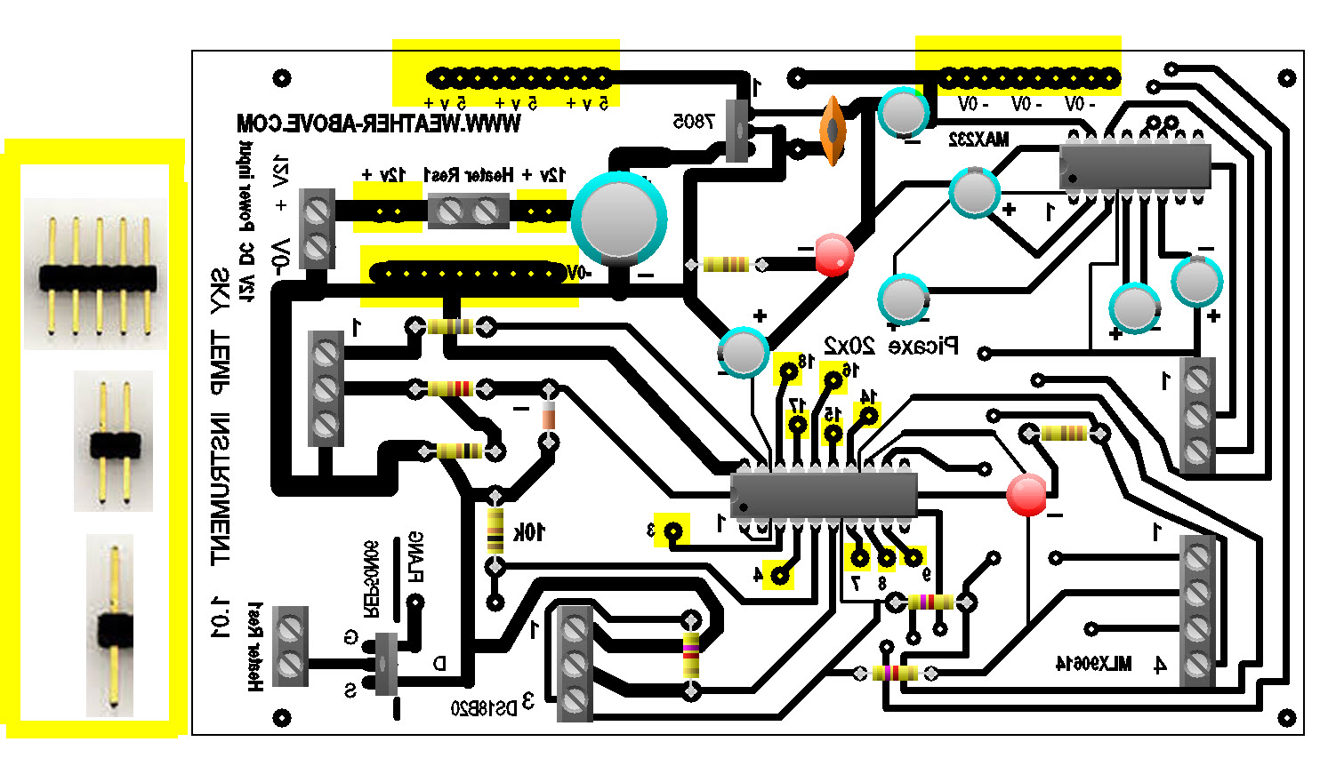
To allow the circuit board to be used for the add-on modules you need to solder header pins for the inputs and voltage output
Where the picaxe chip is located , you will need to use single header pins, indicated by the yellow highlighter pen. These are the inputs to be used to connect the add-on modules, the other long header strips are for auxiliary 5 V DC power and 0 V rails this is where the add-on modules can get their power from, This will be looked at in more detail when we connect the add-on modules
X-ray view of the components,
header pins location
Schematic artwork, Circuit board artwork where redrawn from diagrams supplied by "Niko of weather-watch" functional test programmes supplied by "Niko of weather-watch" Thank you for all the help. Circuit boards, were made in-house assembled and tested Weather-Above.com